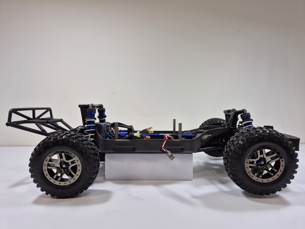
2-2 Chassis Assembly
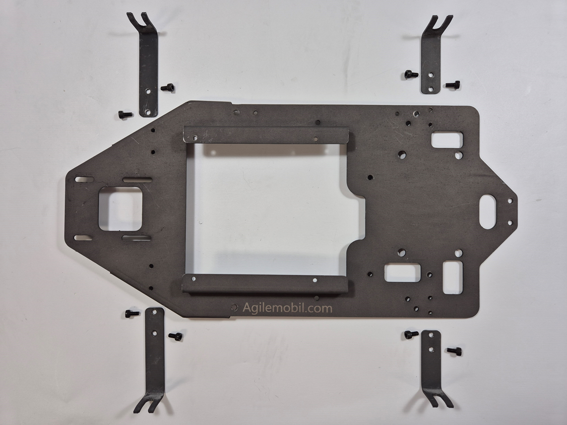
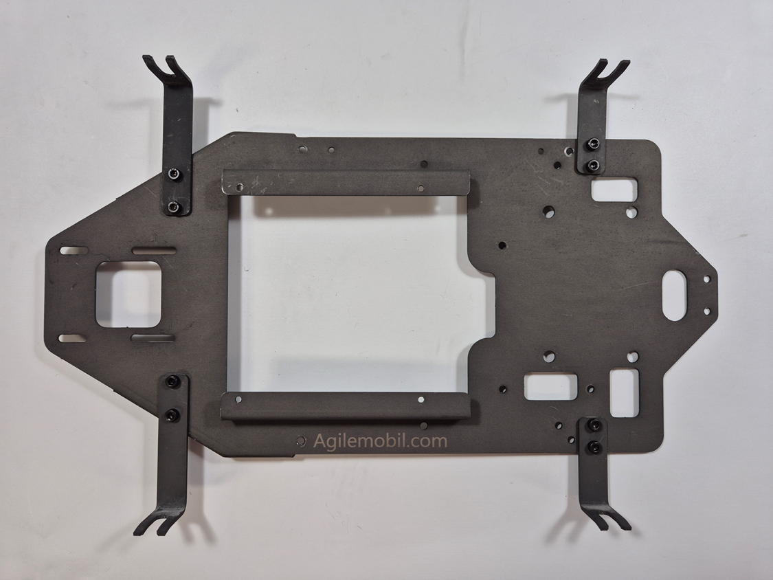
Lower Chassis
Parts (Lower Chassis)
| No. | Part No. |
Name (related Tool) |
Q'ty | Picture |
|---|---|---|---|---|
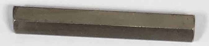
| 1 | F1 | Hex Standoff 6mm x 45mm | 3 |
|
| 2 | F5 |
Hex Bolt M3 x 10L (with T2) |
3 |

|
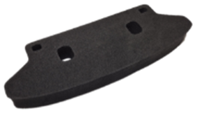
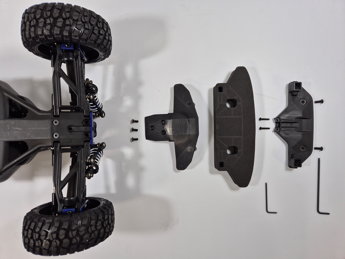
| 3 | X6 | Traxxas Front Bumper Foam | 1 |
|
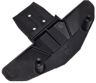
| 4 | X7 | Traxxas Top Cover for Front Bumper Foam | 1 |

|
| 5 | X8 | Traxxas Bottom Cover for Front Bumper Foam | 1 |
|
Tools (Lower Chassis)
| No. | Tool No. |
Name (related fastener) |
Q'ty | Picture |
|---|---|---|---|---|
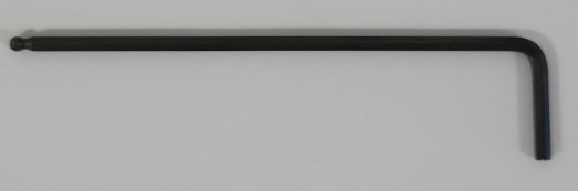
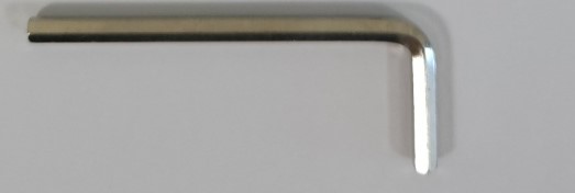
| 1 | T2 |
Hex Wrench 2mm (for F5) |
1 |

|
| 2 | T3 | Hex Wrench 2.5mm | 1 |
|
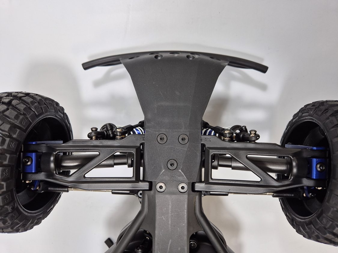
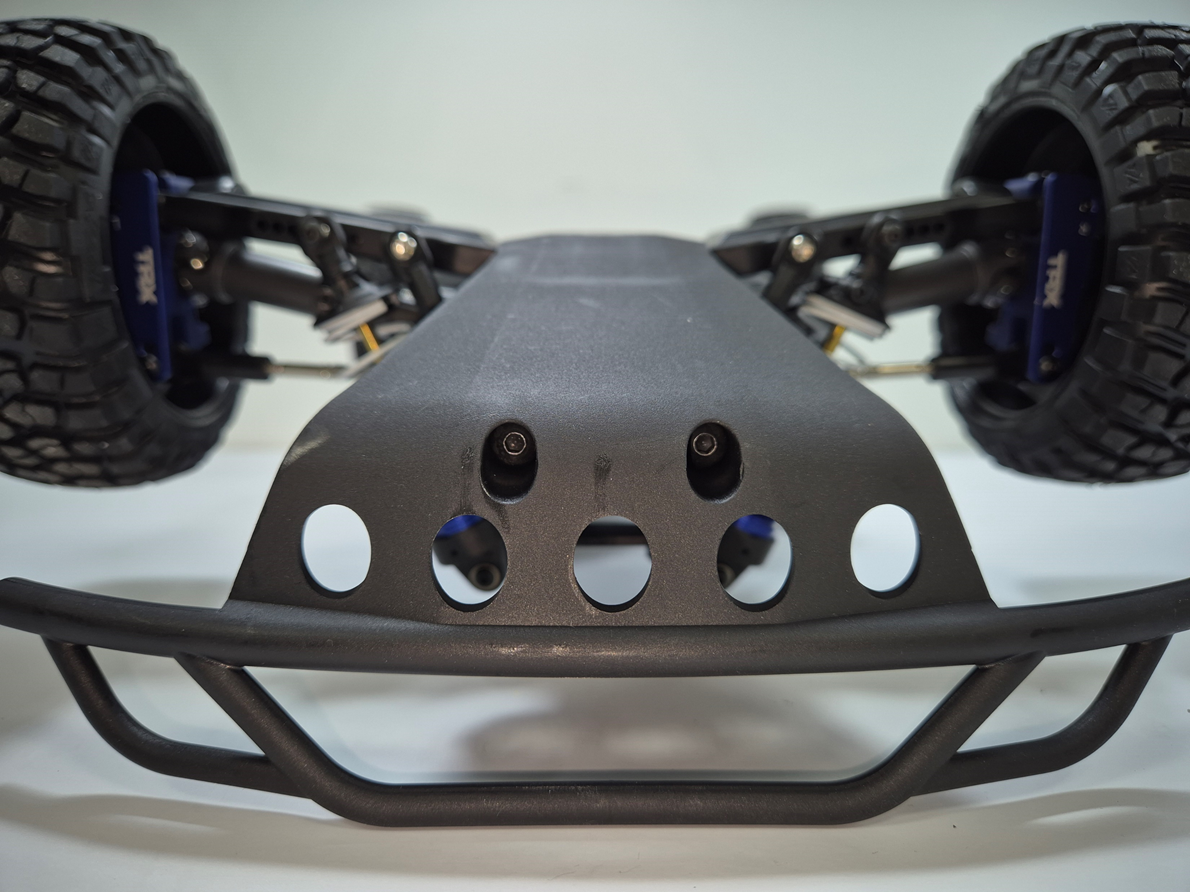
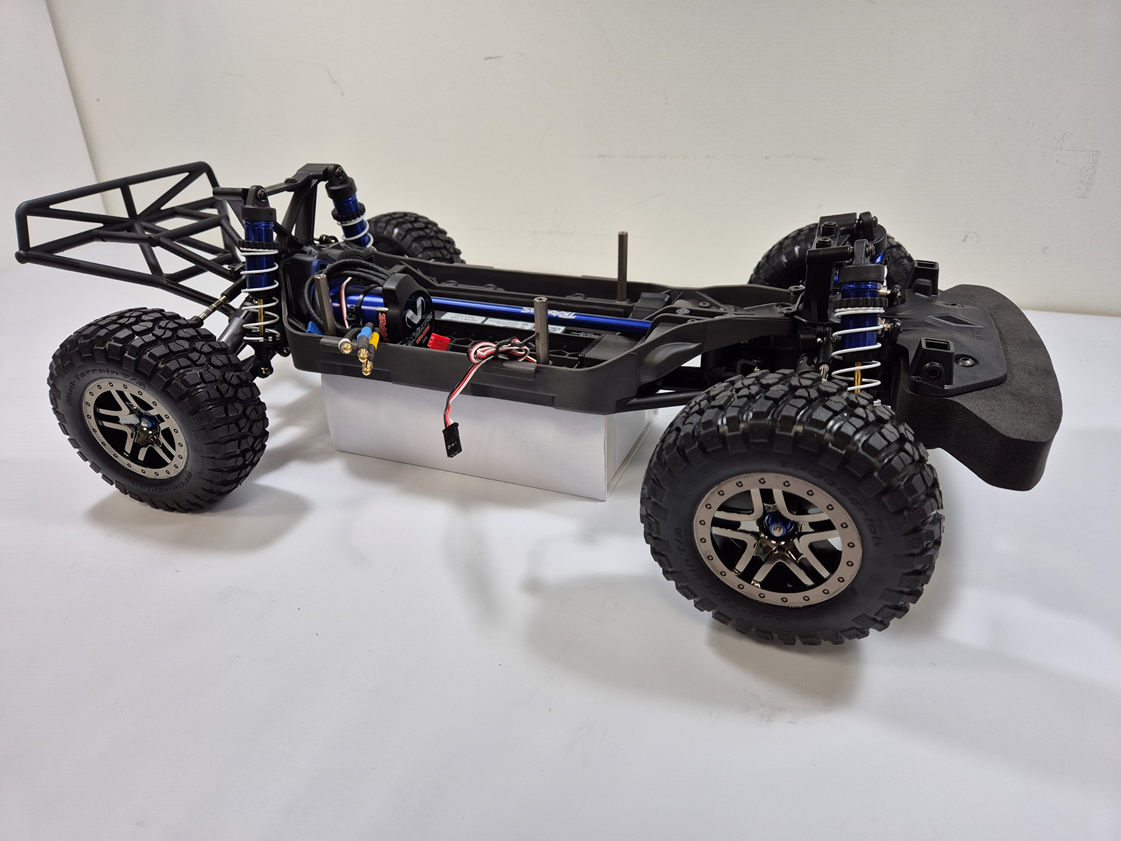
Replacing the front bumper
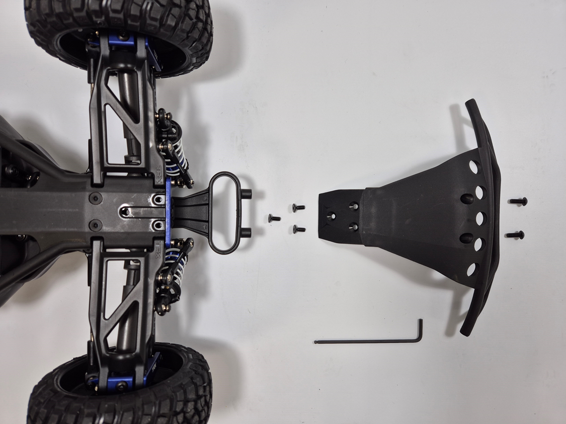
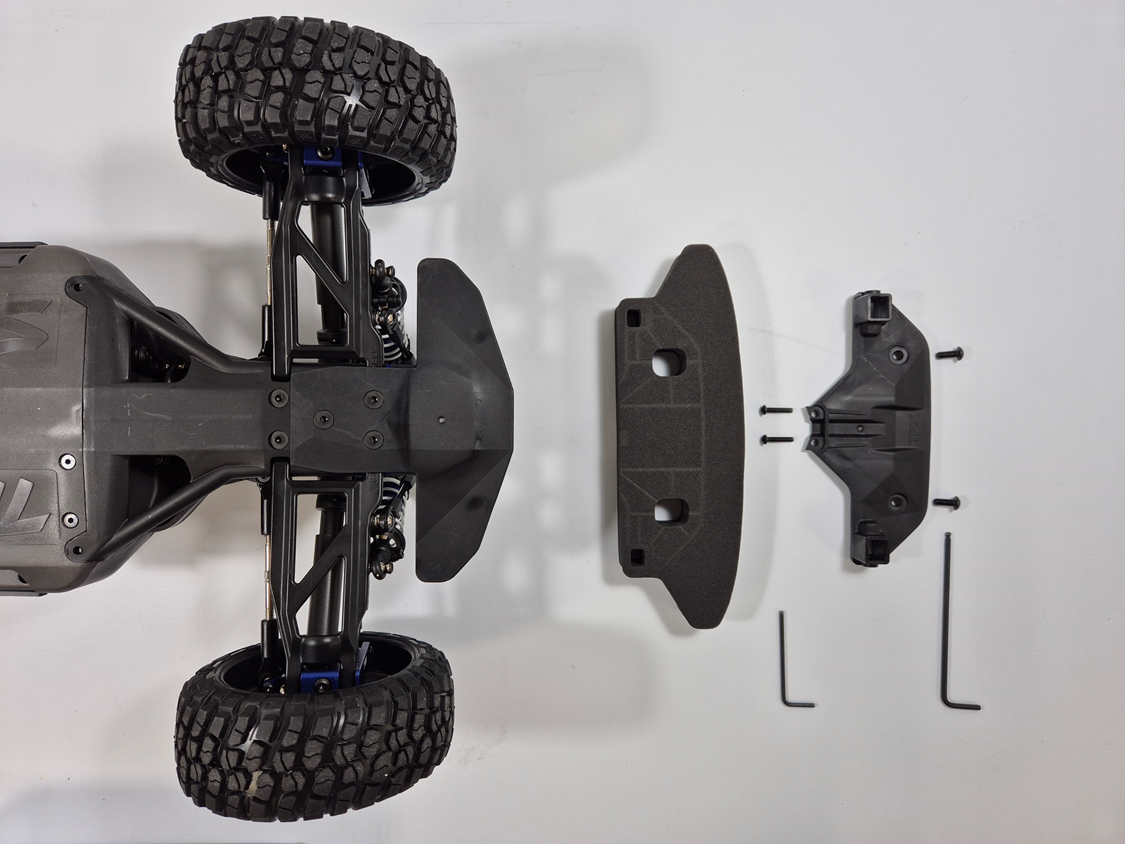
The Original Front Bumper
Bottom view (left) and Upside downed Front view (right)
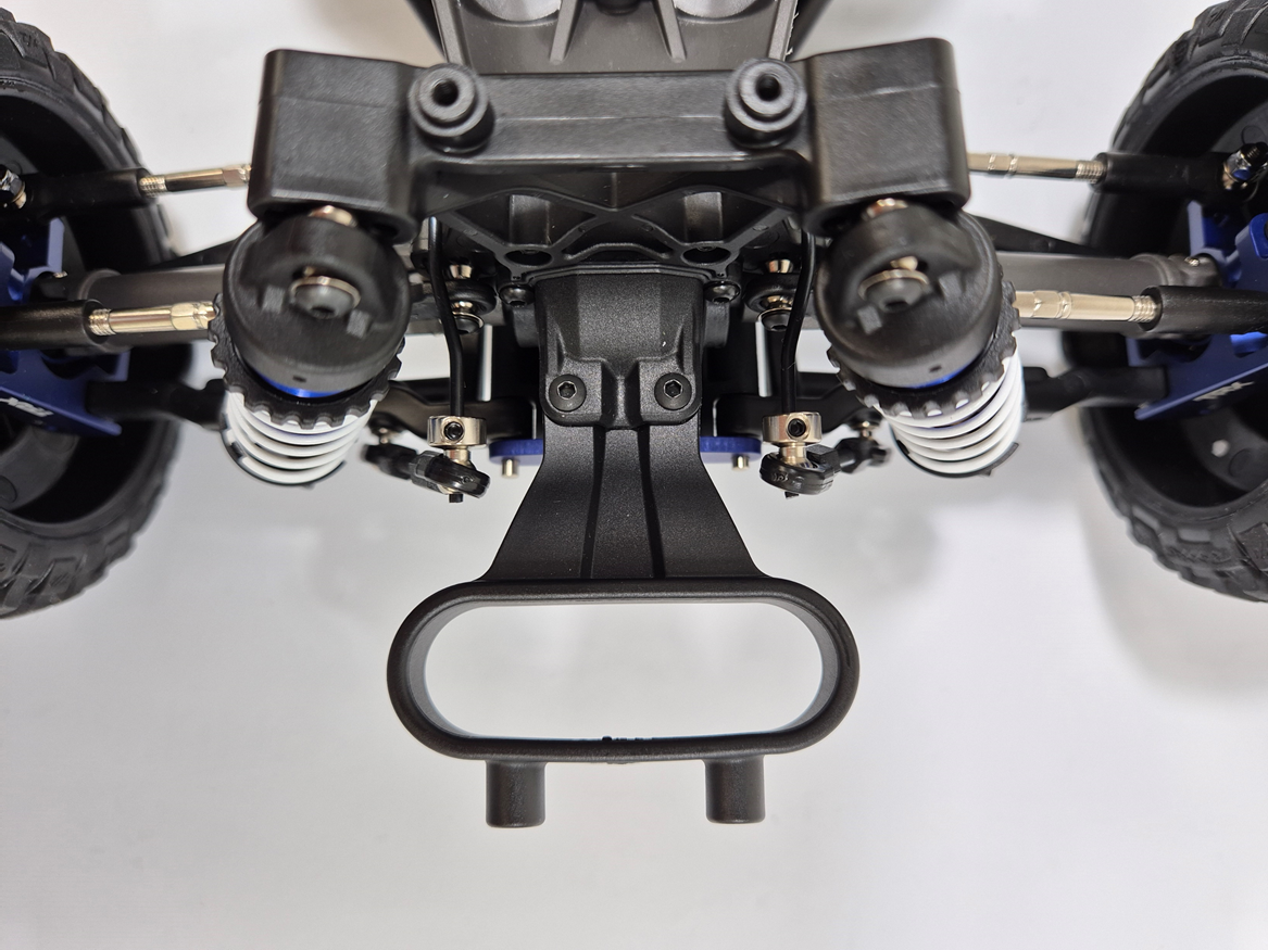
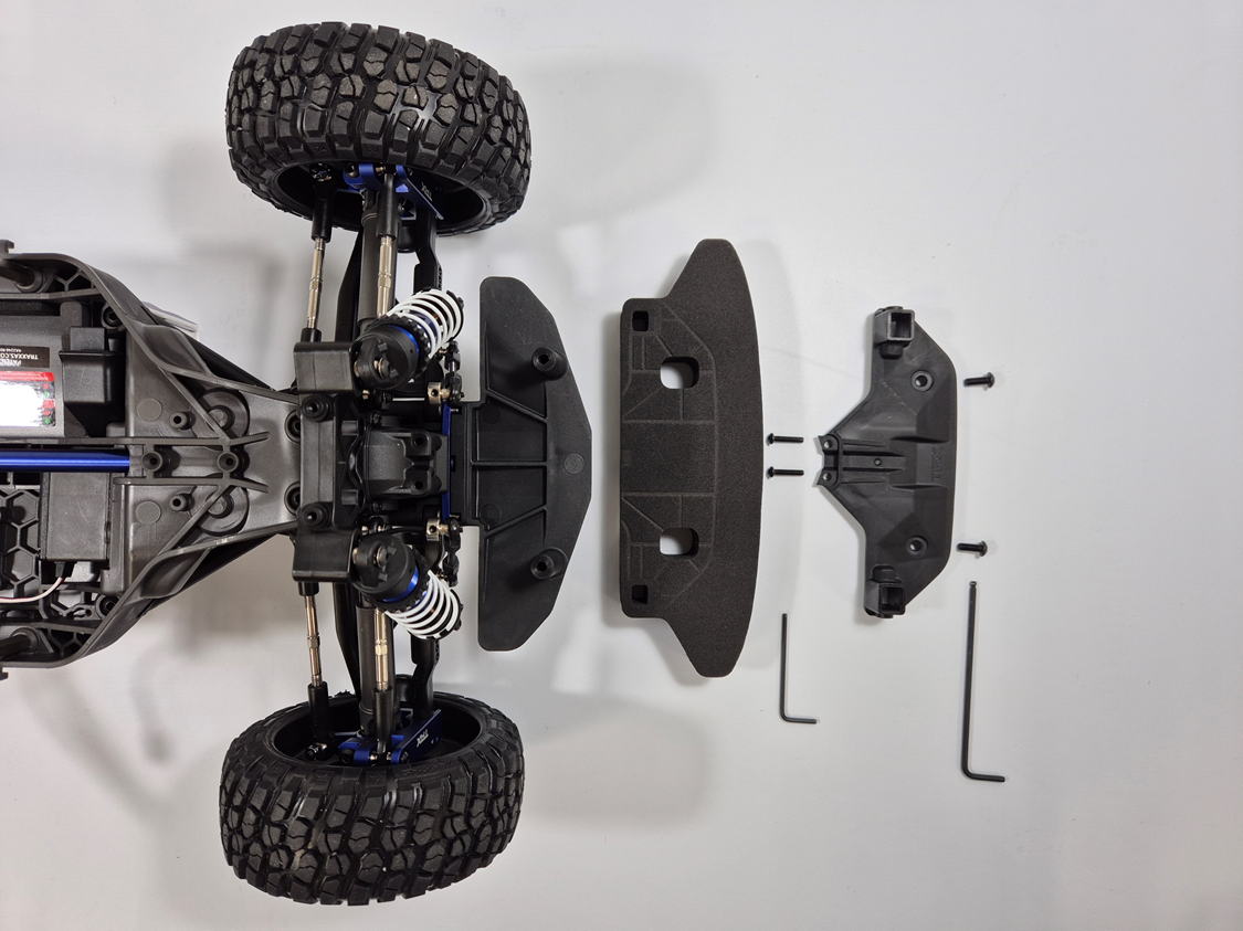
Disassembling front bumper
Partially disassembled front bumper (left) and the remaining part (right)
Fully disassembled front bumper
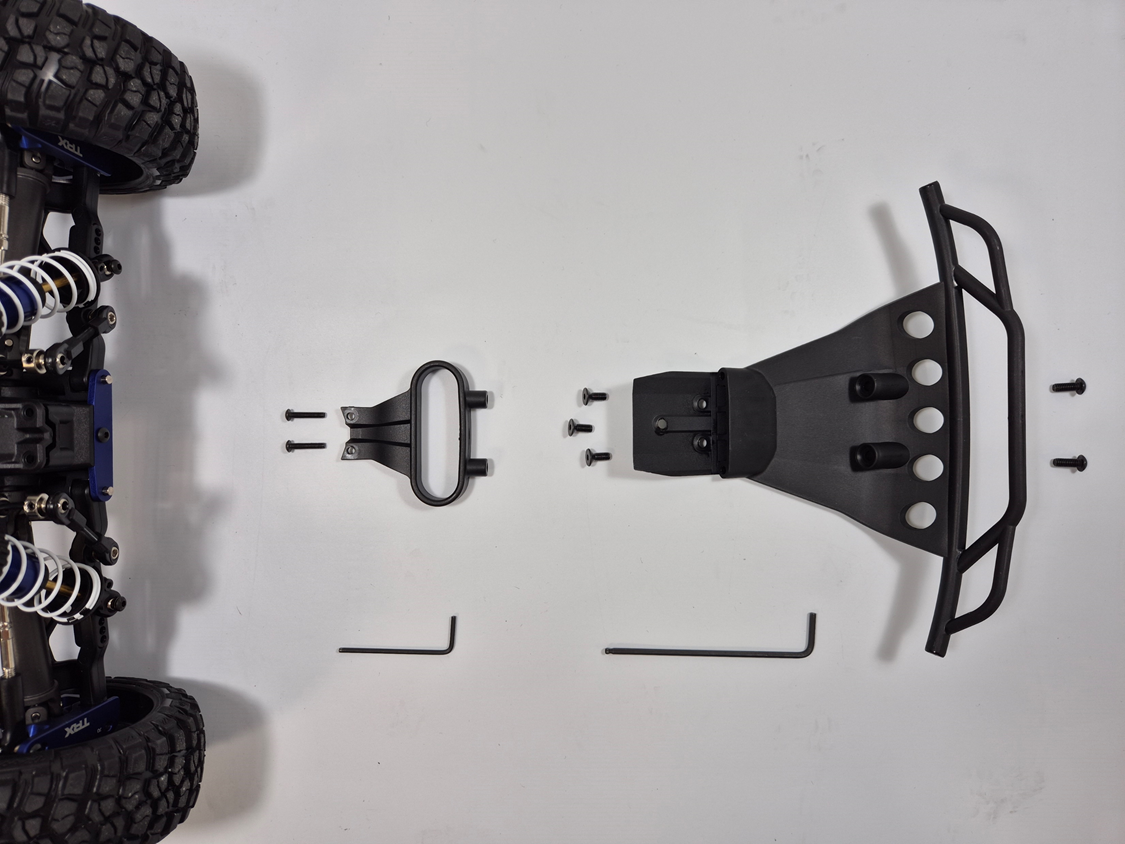
Assemble new front bumper parts step by step
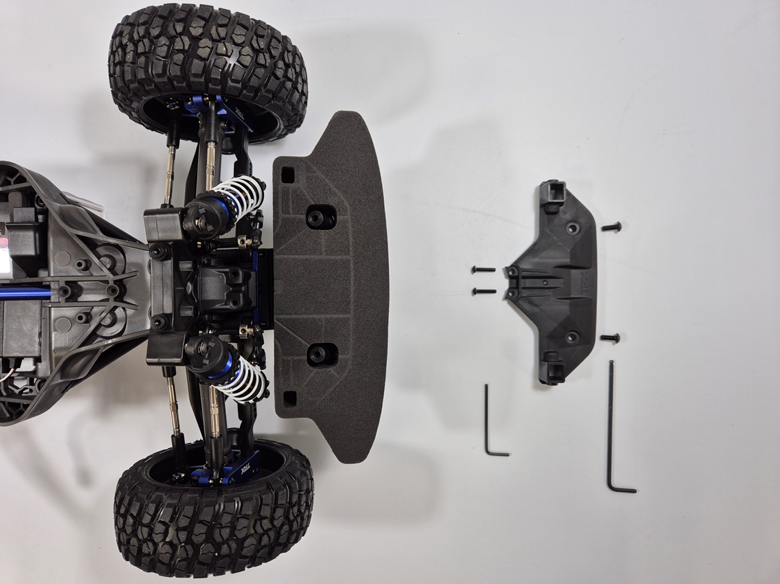
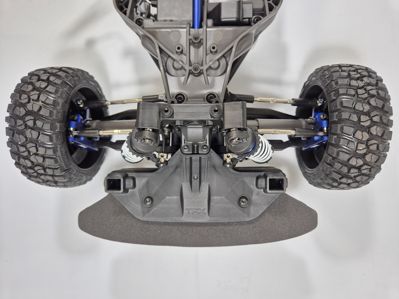
Fully assembled new front bumper (top view)
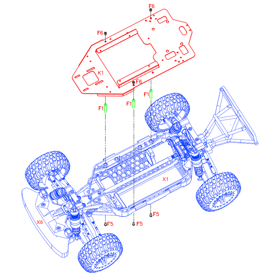
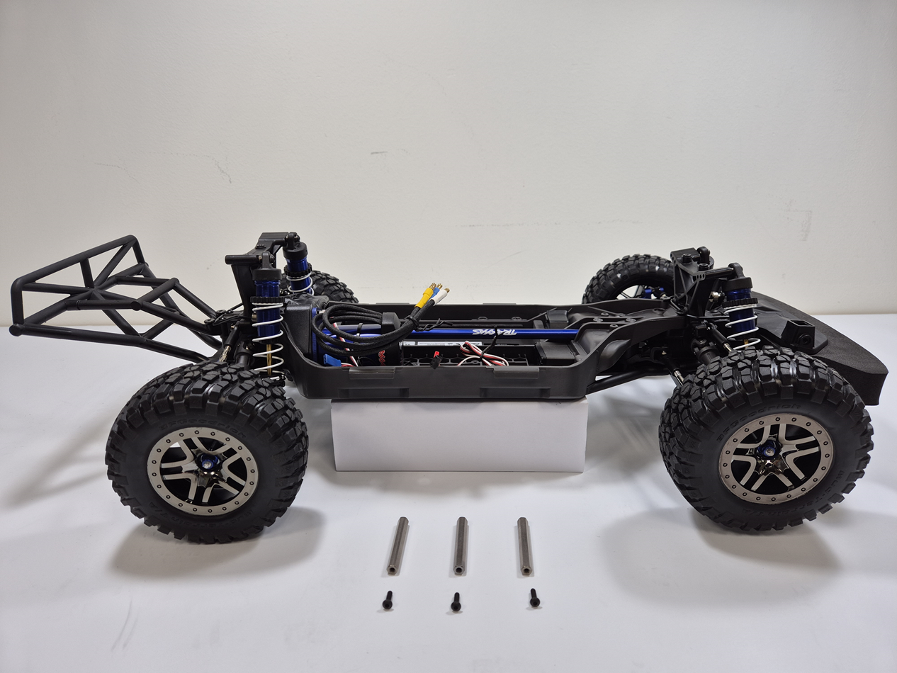
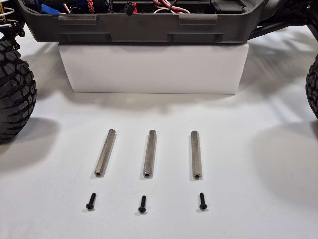
Assemble three standoffs to the lower chassis.
Three standoffs (F1), bolts (F5) and Hex Wrench 2mm (T2)
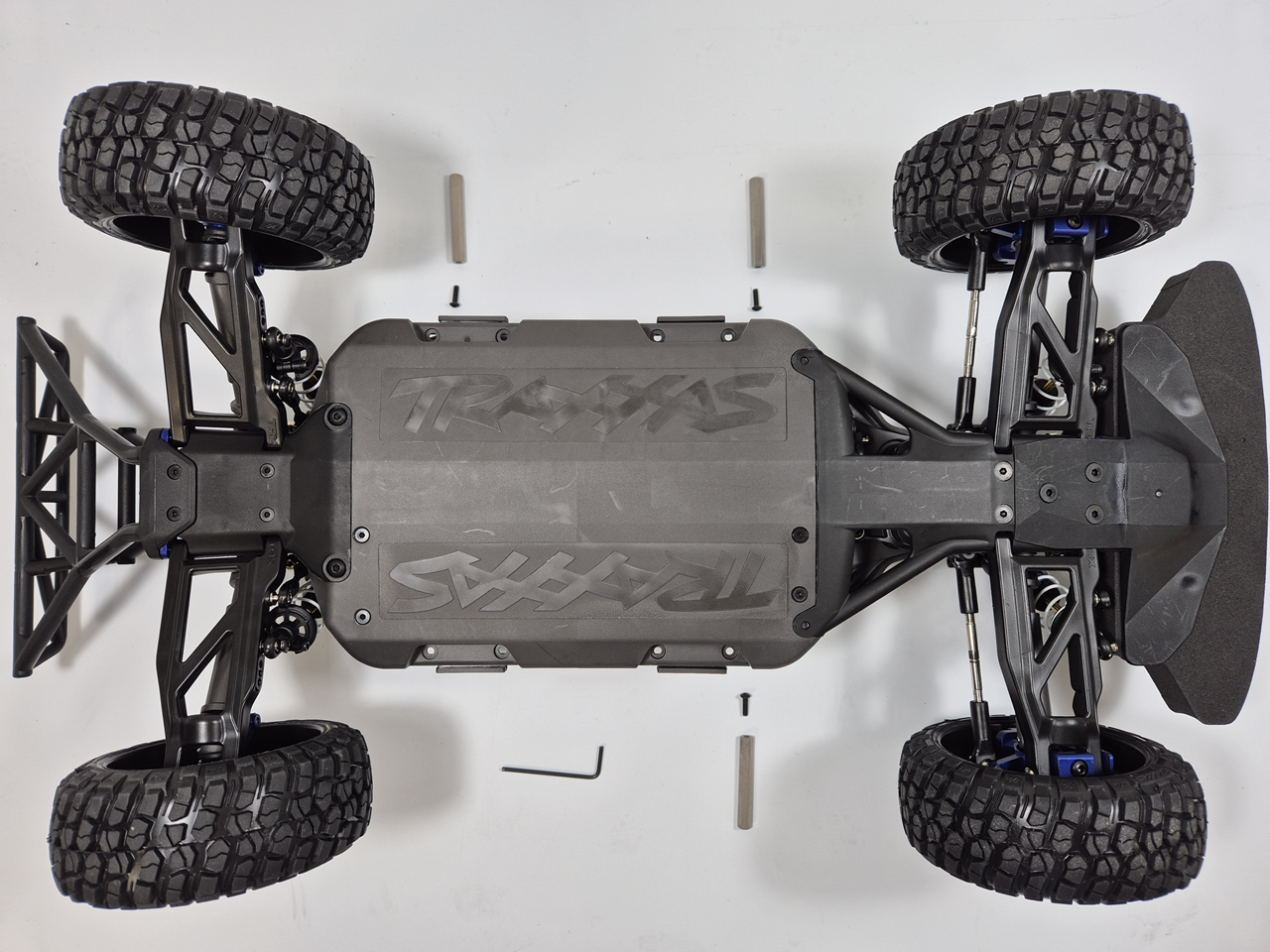
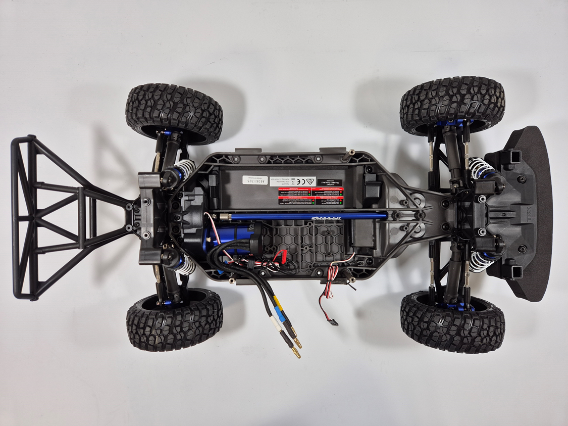
standoffs assembled to the lower chassis
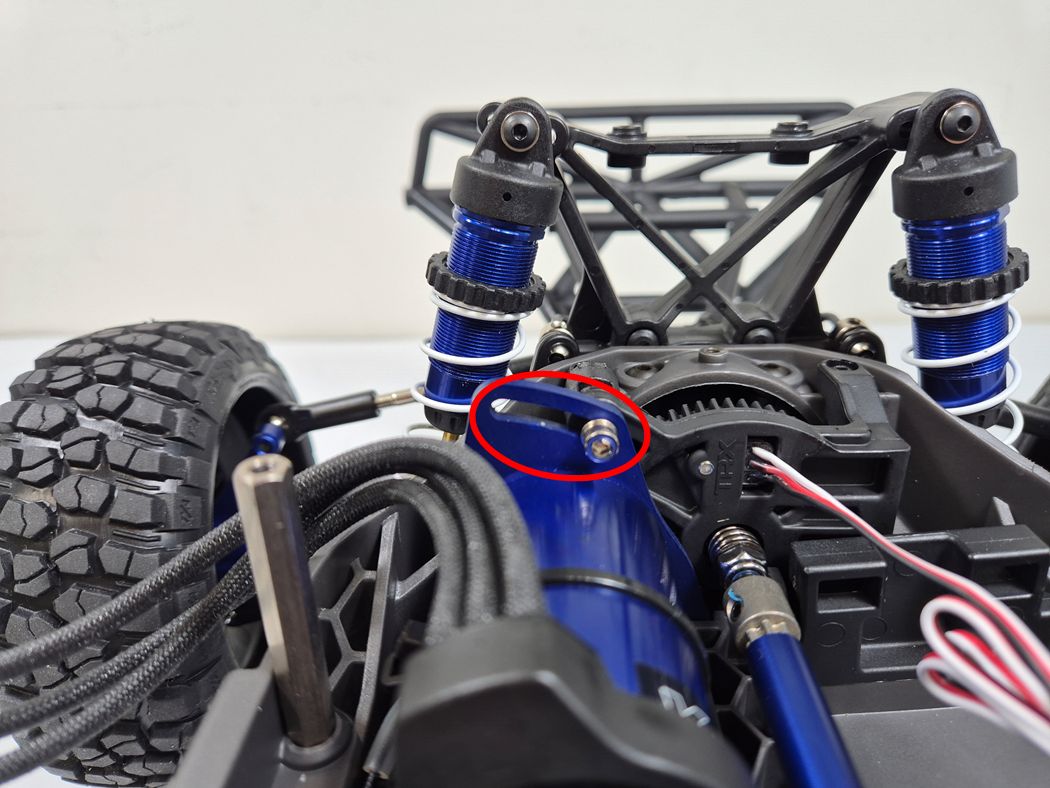
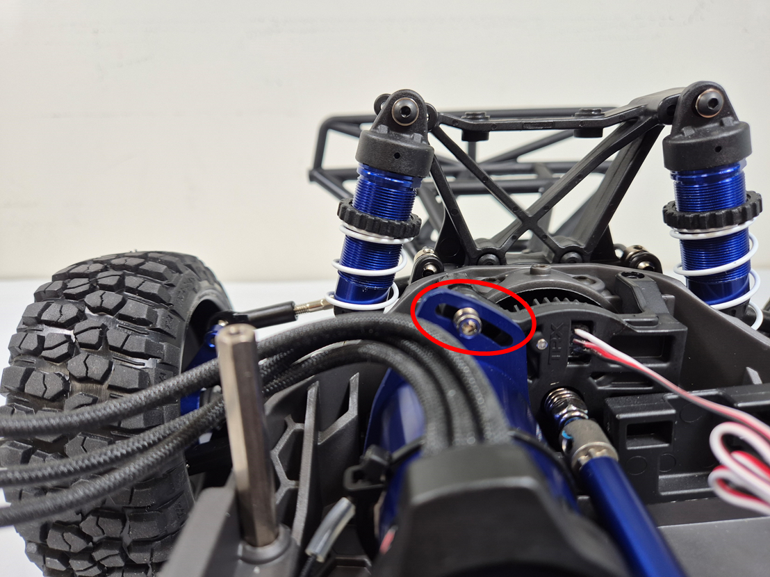
Adjust Traction Motor if necessary
Tools (Adjust Traction Motor if necessary)
| No. | Tool No. | Name | Q'ty | Picture |
|---|---|---|---|---|
| 1 | T2 | Hex Wrench 2mm | 1 |
|
| 2 | T3 | Hex Wrench 2.5mm | 1 |
|
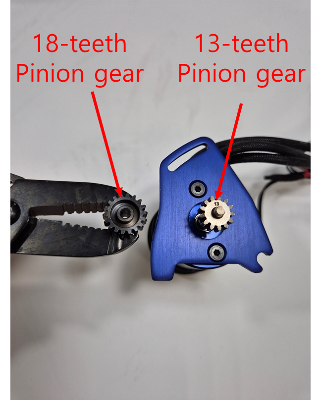
For performance optimization, the meshing between the pinion gear and spur gear of the Traxxas Slash 4x4 can be adjusted.
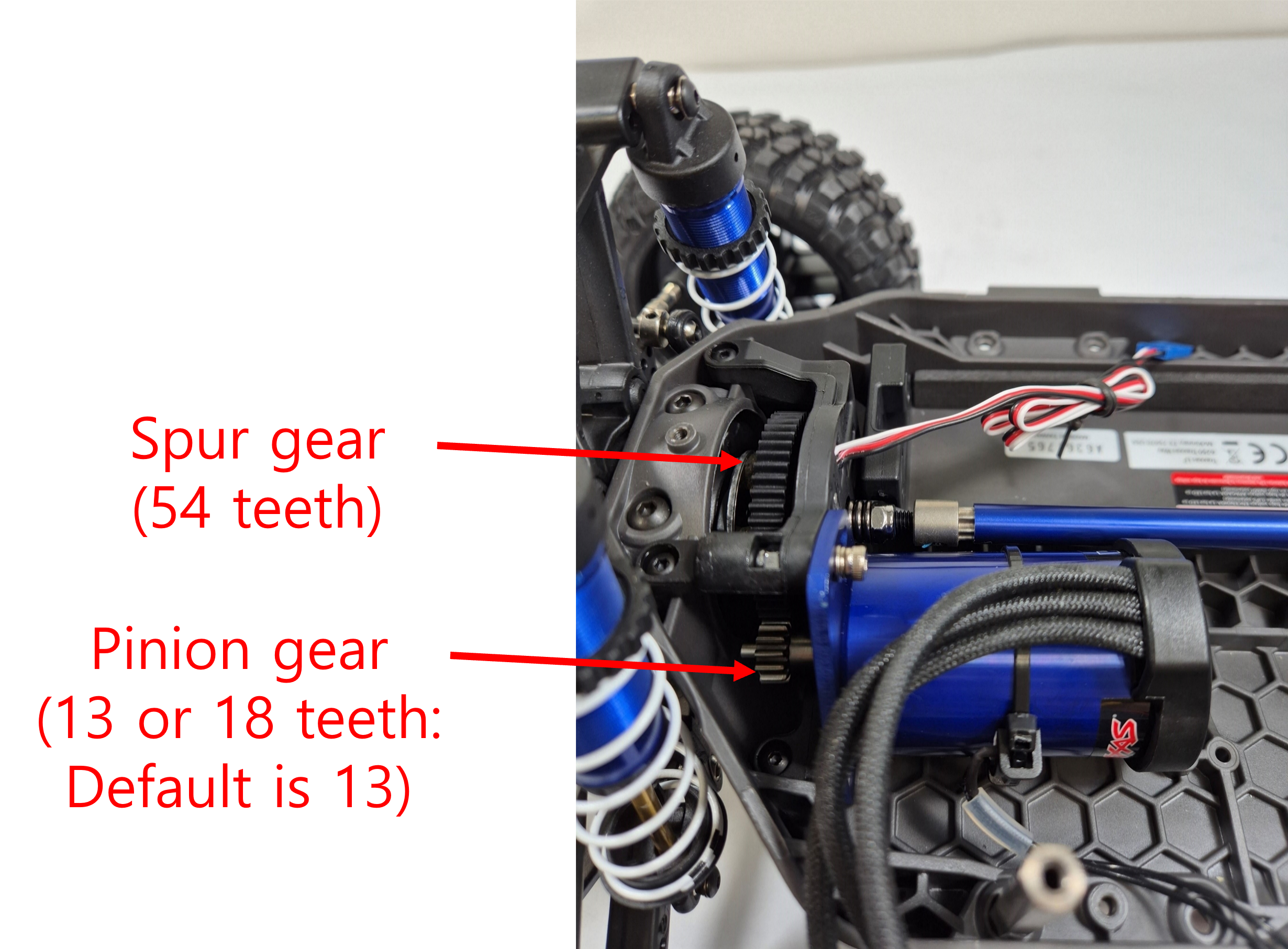
Pinion gear
is not tightly geared up with
Spur gear
Pinion gear
is tightly geared up with Spur gear
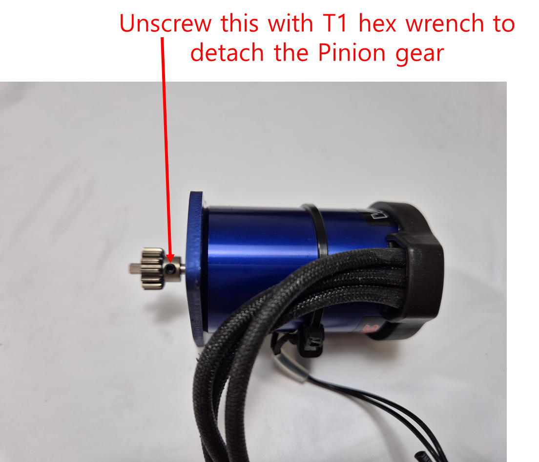
How to
detach
the
pinion gear
from BLDC motor
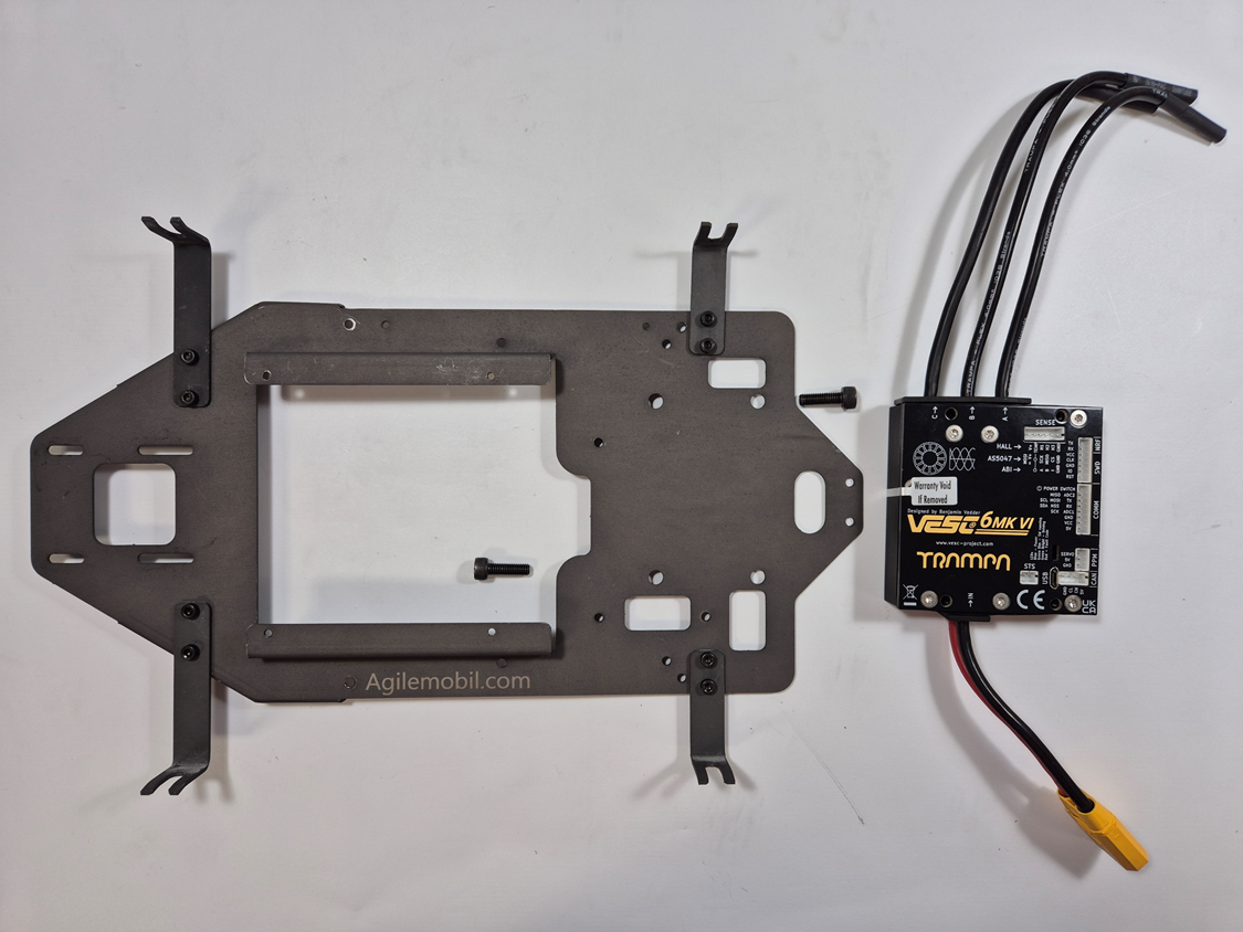
Upper Chassis
Parts (Upper Chassis)
| No. | Part No. |
Name (related Tool) |
Q'ty | Picture |
|---|---|---|---|---|
| 1 | F6 |
Hex Bolt M3 x 6L (with T3) |
19 |

|
| 2 | F10 |
Hex Bolt M5 x 16L (with T5) |
2 |

|
| 3 | F12 | M3 Plain Washer 3.2mm x 0.5mm | 2 |

|
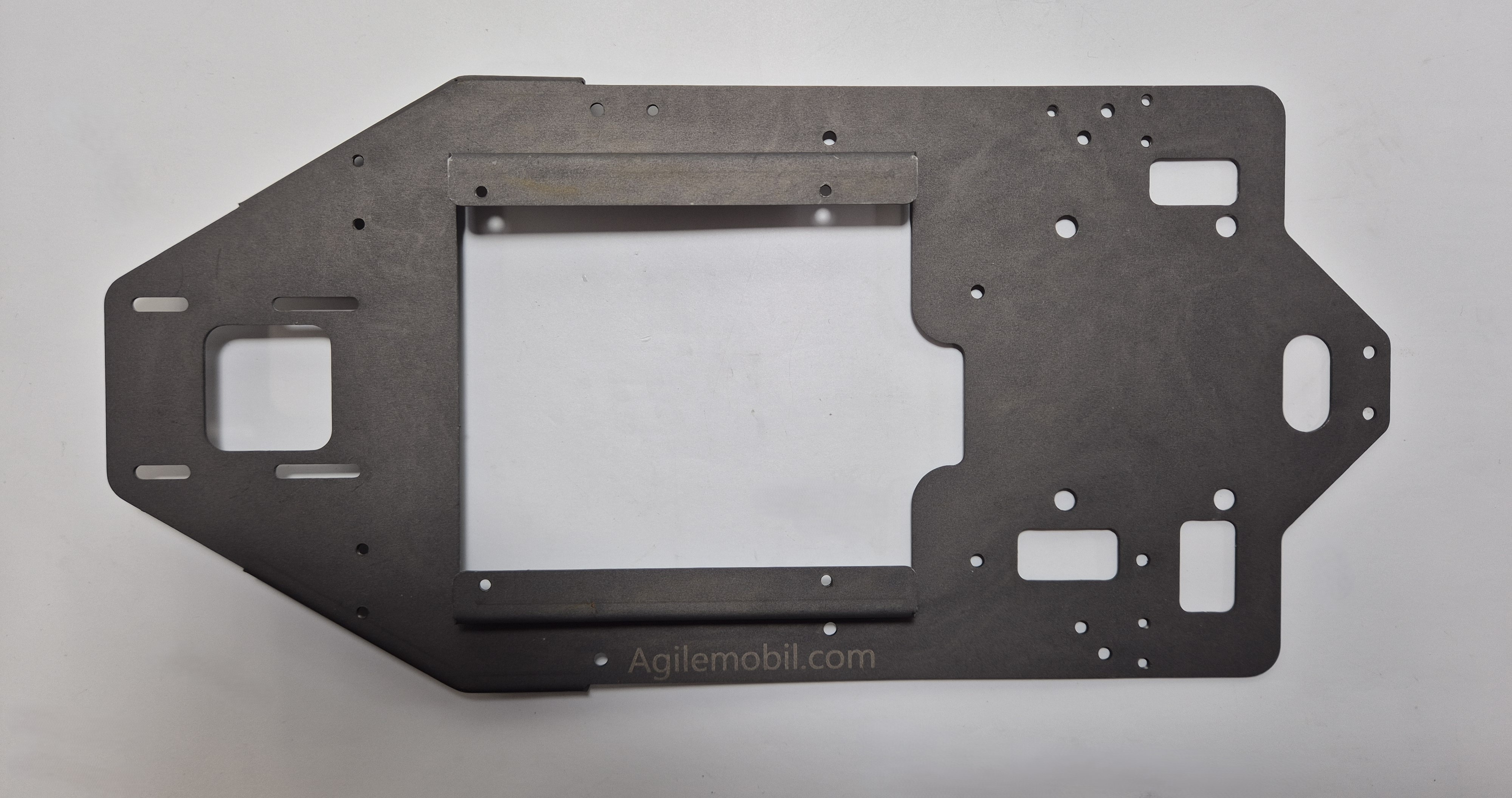
| 4 | K1 | Deck Plate | 1 |
|
| 5 | K14 | Long Wing | 2 |
|
| 6 | K15 | Short Wing | 2 |
|
| 7 | E10 | VESC Controller | 1 |

|
Tools (Upper Chassis)
| No. | Tool No. |
Name (related fastener) |
Q'ty | Picture |
|---|---|---|---|---|
| 1 | T3 |
Hex Wrench 2.5mm (for F6) |
1 |
|
| 2 | T5 |
Hex Wrench 4mm (for F10) |
1 |
|
Wing parts view
Wing parts assembled
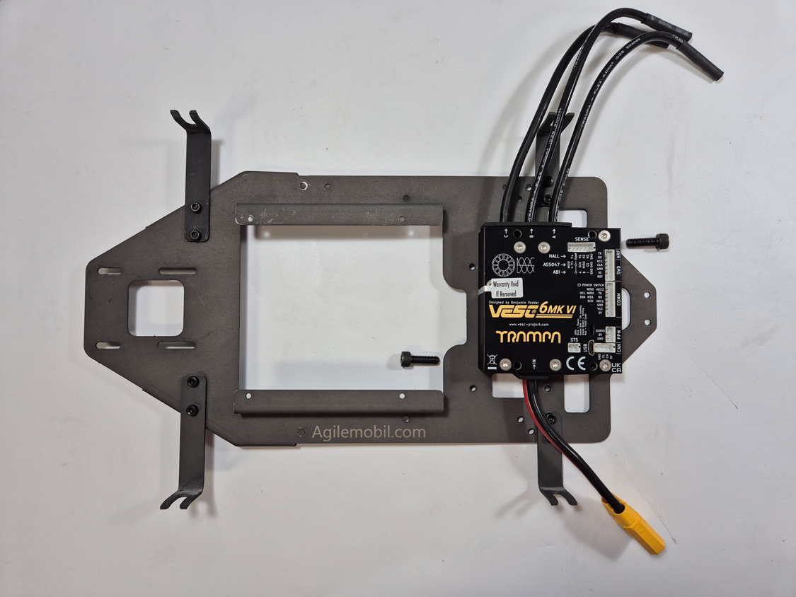
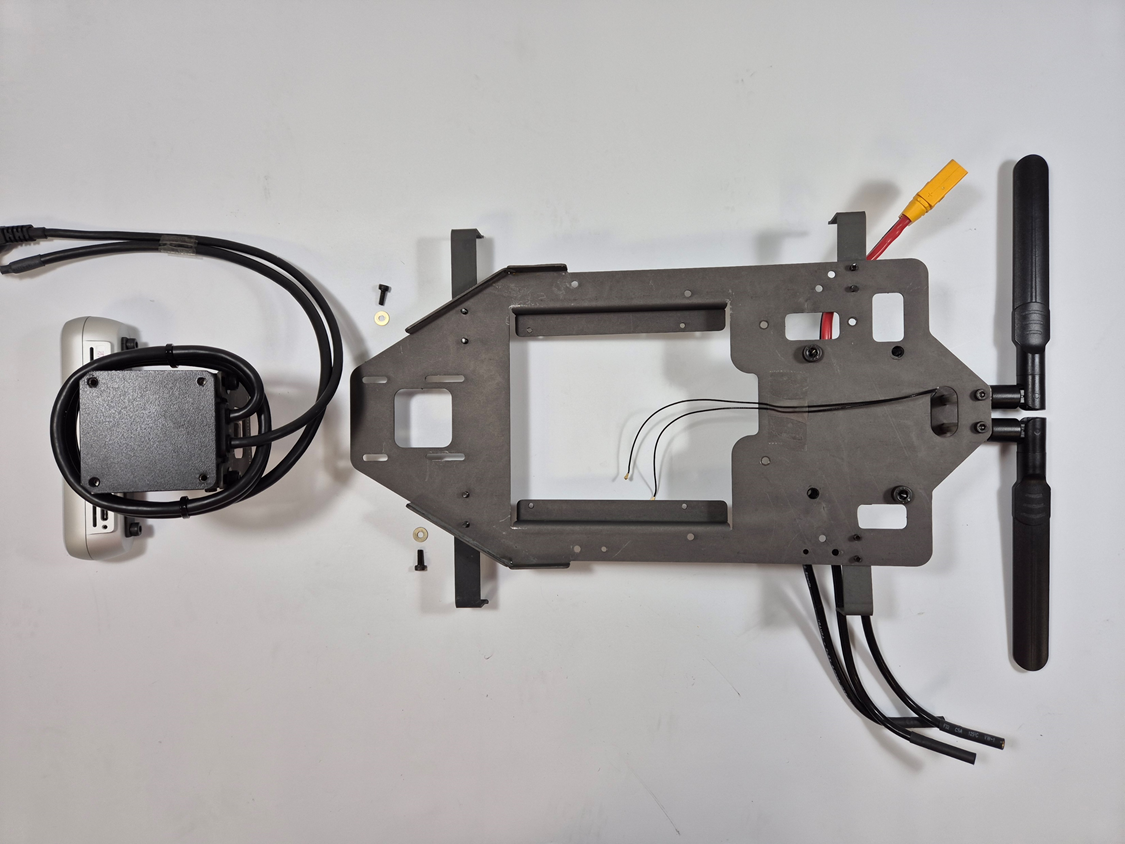
VESC parts view
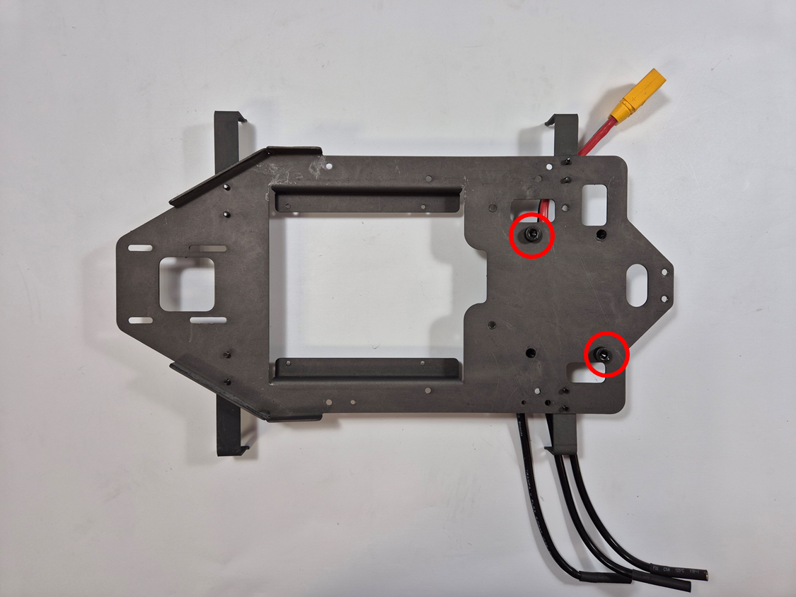
VESC positioned on the deck
VESC assembled on the deck
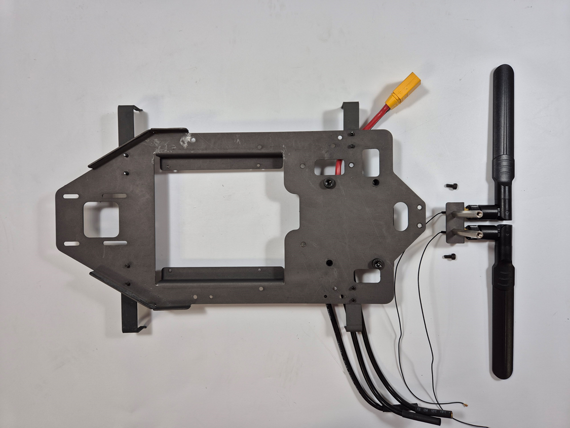
WiFi antenna module parts view
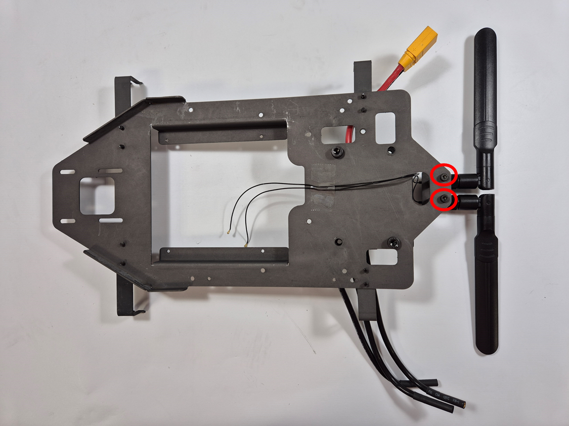
WiFi antenna module assembled on the deck
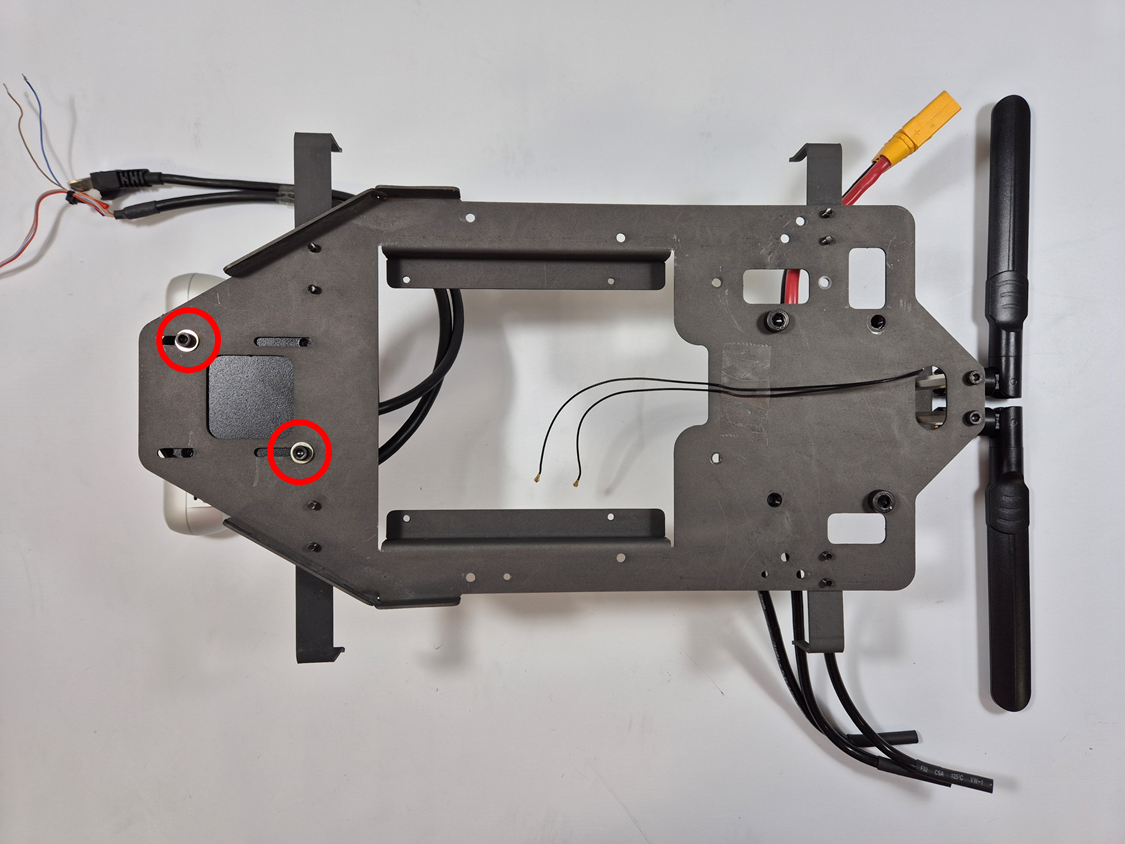
Sensor module parts (F6, F12)
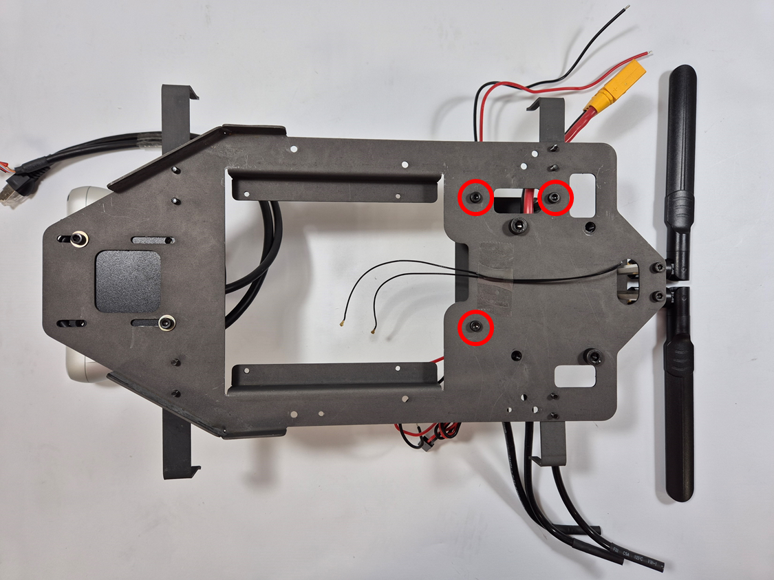
Sensor module assembled
Power module parts view
Power module
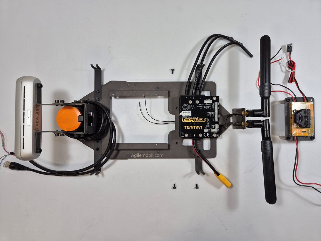
positioned
on the deck
Power module
assembled
on the deck
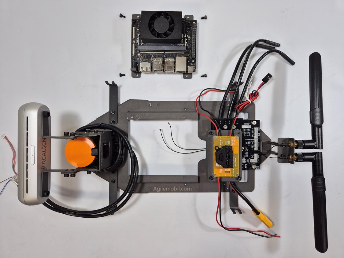
Compute module parts
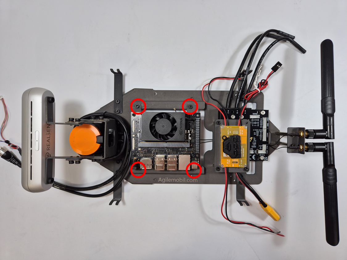
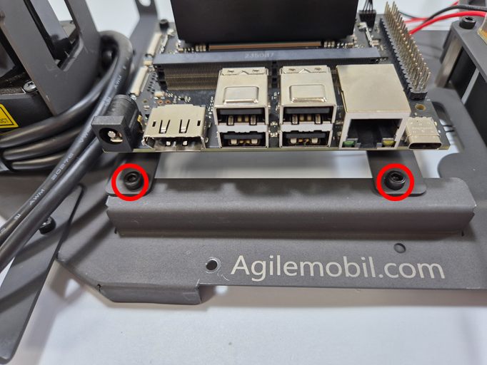
Compute module assembled on the deck
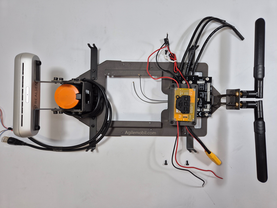
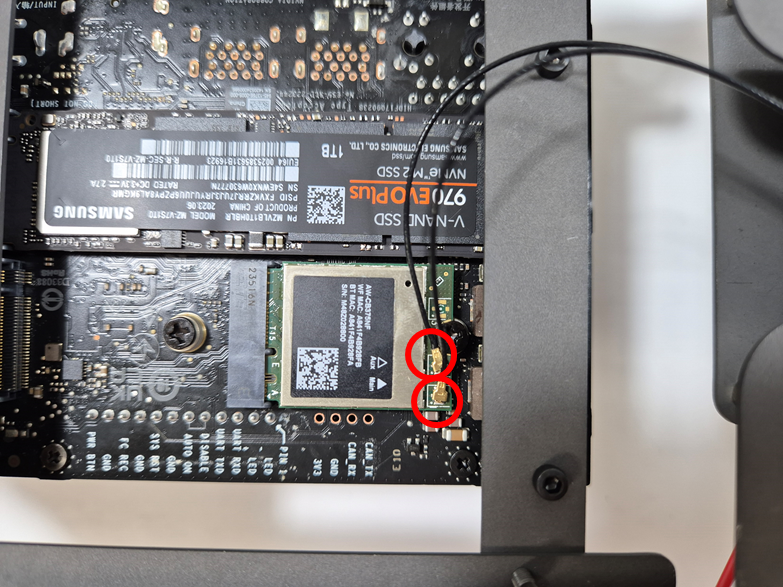
WiFi antenna cables connected
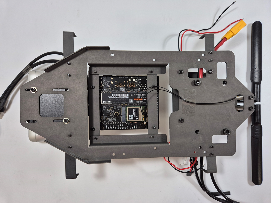
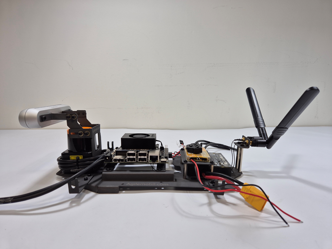
All modules assembled
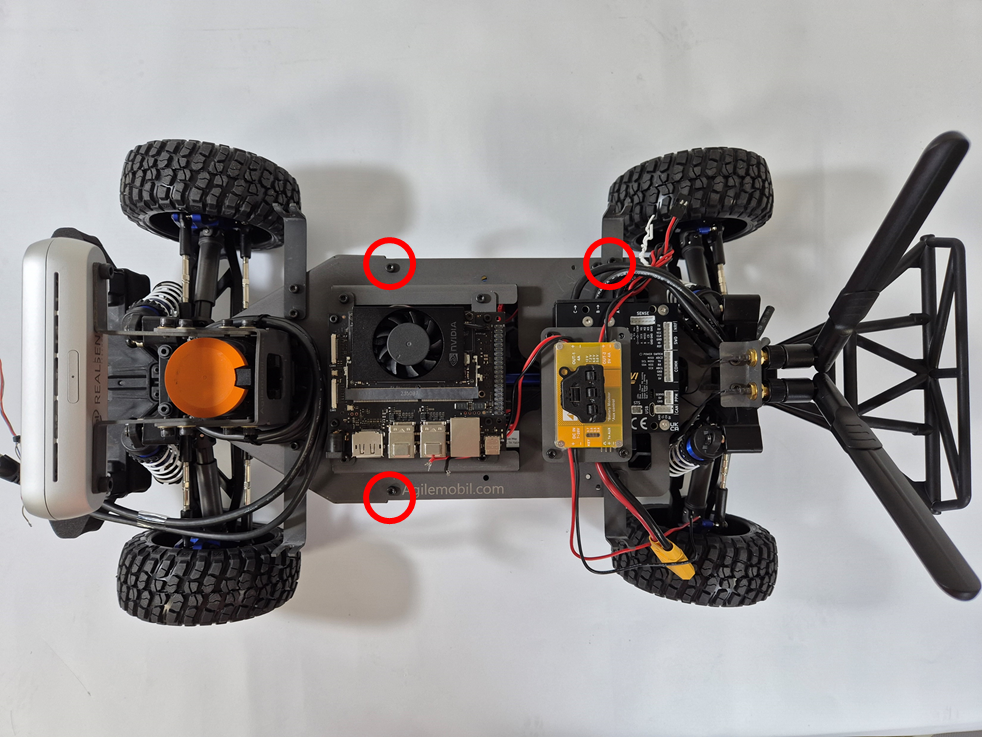
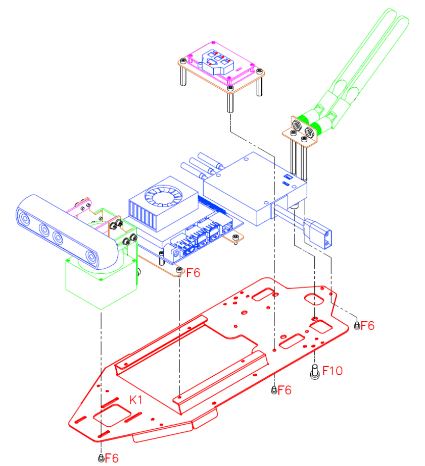
Upper Chassis + Lower Chassis
Parts (Upper Chassis + Lower Chassis)
| No. | Part No. |
Name (related Tool) |
Q'ty | Picture |
|---|---|---|---|---|
| 1 | F6 |
Hex Bolt M3 x 6 (with T3) |
3 |
|
Tools (Upper Chassis + Lower Chassis)
| No. | Tool No. |
Name (related fastener) |
Q'ty | Picture |
|---|---|---|---|---|
| 1 | T3 |
Hex Wrench 2.5mm (for F6) |
1 |
|
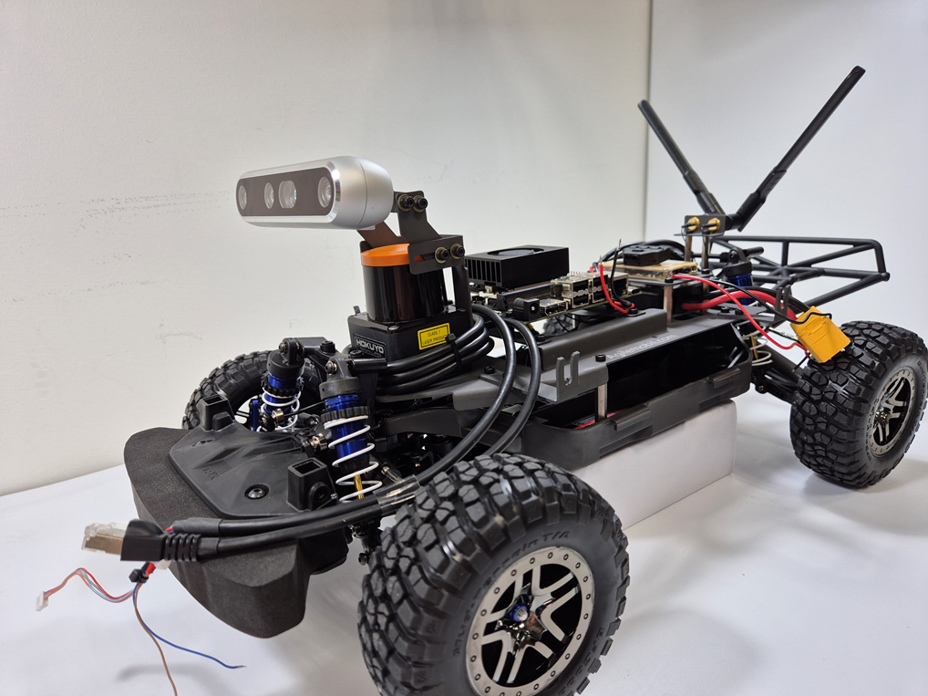
Both chassis to be assembled
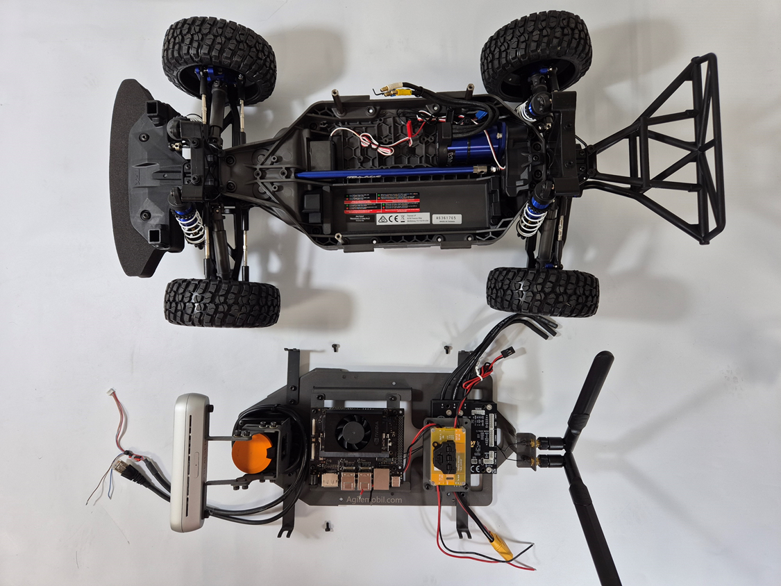
Both chassis assembled together